LED Brightness Control with Potentiometer using ESP32 DOIT DevKit v1

Introduction
An LED can be turned ON or OFF using a digital pin, but controlling its brightness requires PWM (Pulse Width Modulation). The ESP32 supports PWM on almost all GPIOs, which makes it easy to adjust LED brightness smoothly.
In this tutorial, we’ll use a potentiometer (GPIO 34) to control the brightness of an LED (GPIO 12). Turning the potentiometer knob will increase or decrease the LED brightness.
Components Required
- ESP32 DOIT DevKit v1
- Potentiometer (10kΩ)
- LED
- 220Ω resistor (to protect LED)
- Breadboard and jumper wires
- USB cable
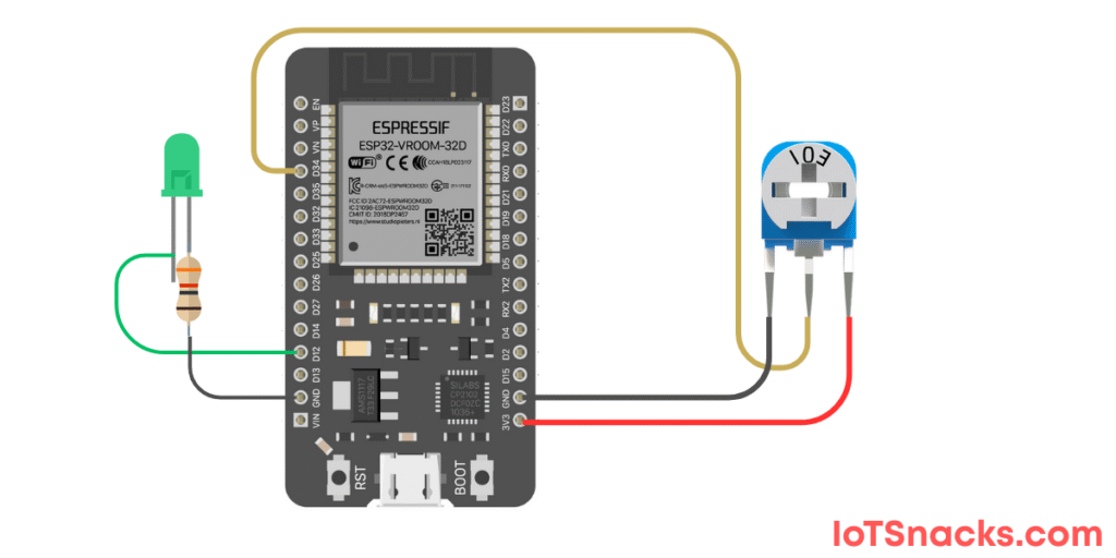
Circuit Diagram
- Potentiometer VCC → 3.3V
- Potentiometer GND → GND
- Potentiometer Wiper (middle pin) → GPIO 34
- LED + (anode) → GPIO 12 (through 220Ω resistor)
- LED – (cathode) → GND
Arduino Code
// LED Brightness Control with Potentiometer using ESP32 DOIT DevKit v1
// Potentiometer at GPIO 34, LED at GPIO 12

int potPin = 34;   // Potentiometer input pin
int ledPin = 12;   // LED output pin
int potValue = 0;  // Variable to store potentiometer value
int ledValue = 0;  // Mapped value for LED brightness

void setup() {
  Serial.begin(115200);
  pinMode(ledPin, OUTPUT);
}

void loop() {
  potValue = analogRead(potPin);          // Read potentiometer (0–4095)
  ledValue = map(potValue, 0, 4095, 0, 255); // Map to 0–255 for PWM duty cycle

  analogWrite(ledPin, ledValue); // Set LED brightness
  Serial.print("Pot Value: ");
  Serial.print(potValue);
  Serial.print(" | LED Brightness: ");
  Serial.println(ledValue);

  delay(100);
}
Step-by-Step Code Explanation
Define Pins and Variables
int potPin = 34;
int ledPin = 12;
int potValue = 0;
int ledValue = 0;
Assign GPIO 34 for potentiometer input, GPIO 12 for LED output.
Setup
Serial.begin(115200);
pinMode(ledPin, OUTPUT);
Start Serial communication and configure LED pin as output.
Read Potentiometer
potValue = analogRead(potPin);
Reads potentiometer value (range 0–4095).
Map Pot Value to LED Brightness
ledValue = map(potValue, 0, 4095, 0, 255);
Maps potentiometer values (0–4095) to PWM range (0–255).
Set LED Brightness
analogWrite(ledPin, ledValue);
Controls LED brightness based on potentiometer position.
Serial Monitor Debugging
Serial.print("Pot Value: ");
Serial.print(potValue);
Serial.print(" | LED Brightness: ");
Serial.println(ledValue);
Displays both raw potentiometer and mapped LED values.
Output
- Open Serial Monitor → See potentiometer values and mapped brightness.
- Rotate knob left → LED gets dimmer.
- Rotate knob right → LED gets brighter.
Real-Life Applications
- Light Dimmer Switch – control LED or bulb brightness.
- Fan Speed Control – adjust motor speed with potentiometer.
- Audio Control – change sound volume in DIY projects.
- IoT User Interface – physical knob to adjust settings.
Troubleshooting
| Problem | Cause | Solution |
|---|---|---|
| LED always ON | Wrong wiring | Check LED polarity + resistor |
| LED doesn’t change brightness | Wrong pin | Ensure LED is on GPIO 12 |
| Values unstable | Loose potentiometer wires | Secure breadboard connections |
| Serial Monitor garbage | Wrong baud rate | Set 115200 baud |
Can I use onboard LED instead of external LED?
Yes, change ledPin to 2, but brightness control may not be smooth since onboard LED is not PWM optimized.
Why use map() function?
Because ESP32 reads analog input as 0–4095, but PWM brightness is controlled in 0–255 range.
Can I control multiple LEDs with one potentiometer?
Yes, just duplicate analogWrite() for each LED pin.
Can I use a different resistor for LED?
220Ω is standard; values between 150–330Ω work fine.
Can I replace potentiometer with LDR or other sensors?
Yes ✅, any analog sensor can be used instead of potentiometer for automatic LED control.