LED Blinking with ESP8266: Step-by-Step Tutorial for Beginners

Introduction
The Blink LED program is the first step for anyone learning micro controllers. With the ESP8266 Wi-Fi micro controller, it’s even more exciting because you can later control LEDs through Wi-Fi and IoT platforms.
In this tutorial, we’ll blink an external LED using ESP8266 and Arduino IDE as in the previous tutorial we explained how to blink onboard LED and . You’ll also get a line-by-line code explanation to make everything crystal clear.
What You Need
- ESP8266 board (NodeMCU, Wemos D1 Mini, etc.)
- Micro-USB cable
- Arduino IDE installed
- Breadboard & jumper wires
- 1 LED + 220Ω resistor (for external LED)
Blinking an External LED
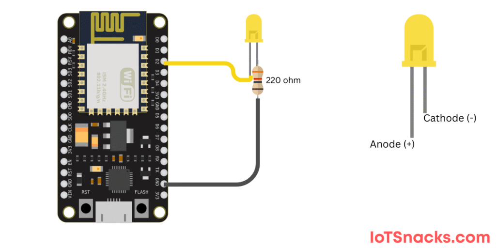
Circuit Diagram :
- Connect D2 (GPIO4) → LED (long leg/anode)
- LED short leg (cathode)→ 220Ω resistor→ GND
Code Example – External LED
// Blink External LED on ESP8266
int ledPin = D2; // External LED connected to D2 (GPIO4)

void setup() {
  pinMode(ledPin, OUTPUT); // Set D2 as output
}

void loop() {
  digitalWrite(ledPin, HIGH); // Turn LED ON
  delay(500);                 // Wait 0.5 second
  digitalWrite(ledPin, LOW);  // Turn LED OFF
  delay(500);                 // Wait 0.5 second
}
Step-by-Step Code Explanation
int ledPin = D2;- We define the LED pin as D2 (GPIO4). This makes it easy to change later if needed.
void setup()- Runs once when the ESP8266 starts.
pinMode(ledPin, OUTPUT);→ sets D2 as an output pin.
void loop()- Keeps repeating automatically.
digitalWrite(ledPin, HIGH);→ sends 3.3V to D2, turning the LED ON.delay(500);→ keeps it ON for 500 milliseconds (0.5 seconds).digitalWrite(ledPin, LOW);→ turns the LED OFF.- Another
delay(500);→ keeps it OFF for 0.5 seconds before repeating.
🔆 The external LED will now blink twice per second.
Step 4: Uploading the Code
- Connect ESP8266 to your computer via USB.
- Select the correct COM port in Arduino IDE.
- Click the Upload button.
- Watch the onboard or external LED blink! 🎉
Common Errors & Fixes
- Board not detected? → Install USB driver (CH340/CP2102).
- LED not blinking? → Check GPIO pin mapping and wiring.
- Upload error? → Select the correct board and COM port.
Real-Life Applications
- Status indicators for Wi-Fi connection
- Debugging in IoT projects
- Smart light control systems
- Notifications (e.g., LED blinks when new data is received)
Conclusion
Blinking an LED with ESP8266 is the Hello World of IoT projects. You learned:
- How to blink the onboard LED
- How to blink an external LED with GPIO pins
- Step-by-step code explanation for better understanding
Now that you know how to control LEDs, you’re ready to move on to sensors, relays, and full IoT automation projects. 🚀
Why does ESP8266 onboard LED work in reverse (LOW = ON)?
The onboard LED is wired with inverted logic. LOW turns it ON, HIGH turns it OFF.
Can I use 5V LEDs with ESP8266?
No, ESP8266 works on 3.3V logic. Use resistors to protect LEDs.
Which pins can I use for LEDs?
Safe GPIOs for LEDs: D1, D2, D5, D6, D7 (avoid using D3, D4, D8 for critical tasks).